
The fuse needs to stay intact while the circuit is carrying 5 amps, but needs to blow if anything more than that is conducted. The fuse should blow before the cable overheats, so the cable needs a higher current rating (amps) than the fuse. Fuse size and cable capacity go up in steps, so for this example, I would use 10amp cable with a 7.5amp fuse.
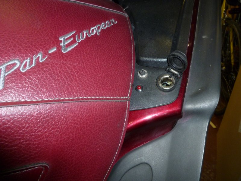 DIN socket on fairing pocket for a heated jacket. |
It is not a good idea to have a socket like this powered all of the
time. Power for this socket and for all of my accessories is obtained
via a master relay. This is fed by a double insulated and protected
30amp cable from the fused side of the main fuse switch near the
battery. In the event of a serious short circuit, the main fuse will blow.
The relay itself is a fused 40amp unit. The Honda accessory harness
has a line which goes live when the ignition is turned on. This is
used to activate the relay.
The socket is mounted below the right hand fairing pocket, and is
activated by a subminature toggle switch. A red LED illuminates when
the switch is on.
Note that a subminature toggle switch does not have the capacity to
switch on/off a heated jacket. A relay is required. The switch
activates the relay, the relay turns on the power to the socket.
Note the polarity. If you connect an LED the wrong way round, it will
destroy it instantly. Best buy 2. You will also need a plastic
housing for it. The anode (+ve lead) is usually the longer of the two.
So make sure you know which one it is before you chop them down to
the same length. Also note that LEDS normally require a resistor to
restrict the voltage that is applied to them. However, some LEDS come
with a resistance built in especially for using in a 12v circuit. Ask
for these. Radio Shack will have them. In the UK, Maplin is probably
the easiest source since Radio Shack withdrew their Tandy outlets
from the UK high street.
|
 The diagram shows a typical relay layout. Look
closely and the connections will be numbered. Pin 30 is the only one
which is not aligned parallel to the side of the relay case. It is
possible to buy fused relays, but since the power is coming from a
fused supply, it isn't necessary. In any case, I like my fuses to be
as close to the battery as possible.
The diagram shows a typical relay layout. Look
closely and the connections will be numbered. Pin 30 is the only one
which is not aligned parallel to the side of the relay case. It is
possible to buy fused relays, but since the power is coming from a
fused supply, it isn't necessary. In any case, I like my fuses to be
as close to the battery as possible.Pins 30 and 87 are opposite each other. These two make or break the circuit for heated jacket. They form the heavy duty switch capable of turning on and off the 5 amps that the jacket draws.
Pins 86 and 85 are opposite each other. In order to turn on the main switch, 12v must be applied across these two.
The main power supply comes into the relay from the right. It is connected to Pin 30. Also connected to pin 30 is our sub-miniature switch. Turn this switch on, and 12v is applied to pin 86. By connecting Pin 85 to the negative supply, the circuit is completed. This creates an electro magnetic field, which activates the main power switch inside the relay for the jacket. You'll hear it click on. The electro magnetic field uses very little power, so sub-miniature switches are easily up to the job. However, don't make the wire for the switch too thin - in the case the lead shorts to earth, you need the wire not to melt before the fuse blows. In fact if there was a short, the fuse will blow very quickly so 3 amp cable would be adequate for the switch connections.
Pin 87 is connected to the centre pin of the fairing socket. When the relay is activated, 12v flows to here and returns to the negative lead via pin 85.
The LED is connected across pins 87 and 85. 87 only has power when the relay is activated. 85 is the negative supply (earth). The LED illuminates only when there is power to the socket.

These pages are merely a personal record of maintaining a
Honda ST1300.
Anyone carrying out similar work should acquaint themselves with the official,
correct procedures or employ the services of a qualified technician.