
There are a few reports on the web as to how the side insert panels from 2008 ST1300 models can be added to earlier machines. All good stuff, but I wanted to avoid i) drilling the castings, ii) attaching anything to the heat deflecting rubbers, iii) Making small individual brackets.
The plastic side panel inserts for the 2008 model will fit quite hapily in the space on the 2006 model, but none of the brackets or threaded lugs exist on the footrest casting or on the frame. So a bit of tweaking is required. Some people have suggested drilling the footpeg holder casting, but this is not to be recommended - interfering with the stress pattern of a casting which carries such a lot of weight can only create problems.
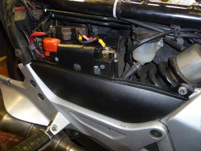
Right Side.
Easy - the old battery cover/main fuse housing is removed and replaced with the new side panel with integral battery cover and fuse housing. The fitting is obvious from the photos. Narrow strips of heavy duty velcro were used to hold the bottom of the insert panel in place. It may become unstuck when the panel is removed, depending on how well the adhesive responds to hot/cold and vibration but there is enough of a downward force when fitted to keep everything firmly in place.
Click the thumbnail to open up the larger image.
|
|
|
|
|
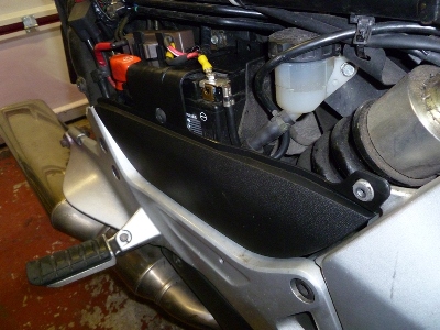
Right panel in place. |
Right panel in place. |
Flash photo to pick out the thin strip of industrial velcro. Normally this is hard to see. The slight tapering of the gap at the top is annoying, but is only noticeable from this angle. It's a function of how the panel fits on the battery and over the bolt lug. |
Left Side.
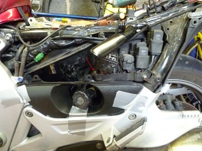
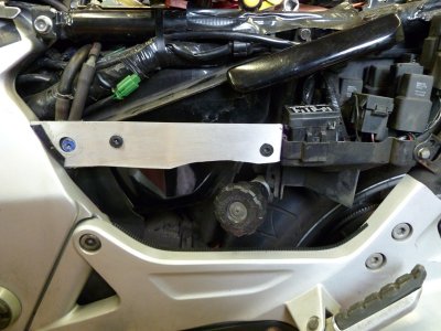
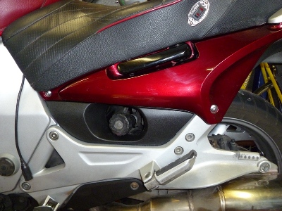
Less easy this. Drilling and tapping the footrest casting was a definite no-no. I opted for a solution involving a 1mm thick aluminium strip to span the space between the fuse box housing at the rear and the front panel lug at the front. Some sheet rubber (ie an old pushbike inner tube) was cut up and impact adhesived to the inside front to prevent rubbing against the cast alloy frame. Rubber was left protruding into the large hole to prevent vibration against the lug.
Holes were drilled to accomodate rubber compression nuts onto which the side panel insert could be attached. The rear of the aluminium strip was bent at 90 degrees to fasten to a captive nut slid over the top of the fuse housing. A rubber grommet was sliced and stuck onto the top side of the front hole in order to prevent any possible vibration. The original side panel squeezes against this, and the original shoulder bolt still tightens up against the lug, so no stress is placed on the original panel.
A thin strip of heavy duty Velcro keeps the bottom of the panel in position. Not that it needed much.
Click the thumbnails for a more detailed photo.
|
|
|
|
|
|
Aluminium strip with rubber compression nuts and protective rubber sheet near. |
Same strip from the reverse side. Note the hole for the fuse housing fitting. Ignore the screwdriver blade in background. |
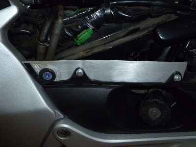
Side insert panel is held in place with tape prior to marking the position of holes for the aluminium strip. Note the captive nut on fuse holder housing is already in place. |
Initial fitting of strip. The strip has moved towards the camera at this point, and gives the illusion of being misaligned. Note the thin velcro strip fitted to the footrest holder casting. |
|
|
|
|
|
|
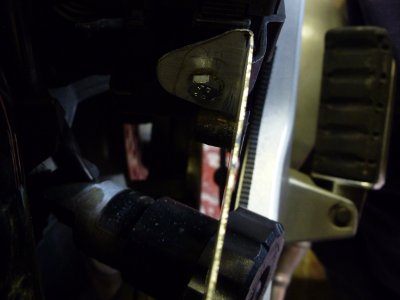
View from above the preload adjuster, looking down on the strip and back to the fuse holder housing. |
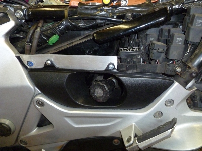
The insert panel mounted in place. The front hole still showing the misaligned, parallax effect ! It fits. Honest. |
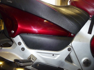
See ? A better photo with the half grommet glued in place. You can just see the edges of the velcro at the base of the panel. |
Side insert panel in place. |
These pages are merely a personal record of maintaining a
Honda ST1300.
Anyone carrying out similar work should acquaint themselves with the official,
correct procedures or employ the services of a qualified technician.