
|
Thumbnail |
Comment |
|
|
1 |
|
Remove Fairing. You need to remove the lower grey cowl and the middle fairing on both sides. Get rid of the seat, and lift the tank as high as it will go without removing the restraining cable. Secure it there. |
|
|
|
Remove Air filter Cover |
|
|
|
Remove Air Filter Housing Base There are 8 Philips head bolts. On mine, the most inaccessible was the one whos head stripped. You need a good screwdriver and a lot of downward pressure to release the screws, and the petrol tank being in the way of applying direct downward pressure doesn't help. The stripped head problem was solved by tapping a slightly oversize normal screwdriver blade into the least damaged part of the head. There are two hoses - front and back - which are held in place with circlips. Slide the circlip well down the tube before removing the tubes and the housing, and remove the circlip afterwards to avoid any chance of these stray bits of metal dropping inside any parts of the engine. The butterfly valves on the throttle bodies act to prevent bits falling into the combustion chamber, but plug them and cover them anyway. |
|
|
|
Tensioner The manual describes a way of making a tool in order to release the tensioner. Basically you need a piece of 1mm thick steel, about 15mm wide. Grind down a blade 4.5mm wide and 19mm long. Grind down a shoulder which is 3mm long and 8.5mm wide. The measurements aren't that crucial as you can see from my version of it. |
|
|
|
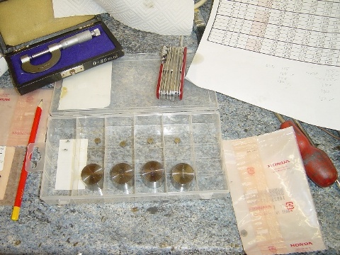
Shims I removed both cam shafts from both sides and placed them into plastic food bags with a slip of paper clearly labelling where each had come from. I did the same with the cam plates and bolts. I kept the valve followers and shims in the engine until I was ready, then dealt with four at a time, placing followers and shims in a plastic screw box with separate compartments. Note the micrometer, the knife with magnifying glass the pencil and planned spreadhseet with shim measurements. The micrometer is needed for measuring shims. i) You can't always read the printed value, ii) the indicated measurement doesn't always match the shim's thickness. My spreadsheet for metric calculations will appear here. |
|
|
|
Link to a valve shim calculator - metric / imperial There are plenty of them out there, this one is a little different and allows you to play around with tolerances. More details from the link - click the picture or choose 'Shim Calculator' from the right hand menu. Metric and Imperial versions available. Excel 2007 format. |
|
|
|
Molybdenum Disulphide Oil. I can't find a source for this in the UK, but then if you read the earlier sections of the service manual, it says to make it yourself with Moybdenum Disulphide and Engine Oil - mixed 1:1. I used the Moly 60 paste (for the rear wheel splines) and engine oil, but I felt 1:1 was too thick, and added about 30% more engine oil. I didn't want a paste that would clog up the lubrication holes in the camshaft. You need this to provide lubrication for the camshaft before the oil gets flowing around the engine again when you first start up. |
|
|
|
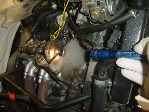
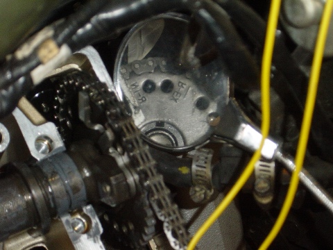
Right Hand Cam - replacing. Put the timing mark on T2. (rotate the crankshaft anticlockwise). You will need a torch and a mirror and a third hand. Make sure that cylinder 2 is at top dead centre. Fit the exhaust cam shaft first. Make sure that the non tensioner side of the cam chain is tight, and rest the cam shaft in its journal bearings. Check the timing marks. The 'R-Ex' mark should line up with the top of the case. The photo on the left shows one way of overcoming the parallax effect, where if you do not look straight on, you can convince yourself that you are a tooth out. Use a torch to project a shadow onto the timing marks. The 2nd photo shows the use of a mirror to establish that the position of the inlet cam is correct. The 'R-In' mark should face outwards. The yellow electrical cable is there to stop the chain falling into the crankcase. Take a look at the path of the chain inside the crankcase. It is possible for the chain to have dropped to the wrong side of the end of a shaft which protrudes. Use a long, clean screwdriver to help manoeuvre it back into position. Also, if you have been turning the engine with the camshafts out, it is possible for the slack cam chains to have slipped off the driving sprocket. When you pick up the chain again, the chain does not wrap around the sprocket properly. Instead, there is an unseen loop under the sprocket, which results in the chain being too tight for the second cam to be located. If either of these happen, re-check the timing mark on the first cam shaft before proceeding to place the second cam shaft. |
|
|
|
Cam Covers - replacing Lubricate the journals and lobes with your MoS2 oil. Refit the Right hand cover. The 4 longer bolts have copper sealing washers, which the manual says, should be replaced. It seems to say that the bolts should be renewed too. The longer bolts are for the four inner holes. Fit the journal cover too - 4 bolts. Mine was difficult to locate by hand, but went on very easily with the downward pressure exherted by finger tightening the bolts. Check the clearances. Make sure the cam chain for the left hand side can move freely, and cannot fall into the crank case and gently turn the engine over with the ratchet (counter clockwise) a couple of times. Return to T1 and check clearances again. |
|
|
|
Left hand Cam Shaft The timing mark should be at T1 with cylinder 1 at top dead centre. Place the inlet cam first keep the non tensioner side of the chain tight when placing the inlet cam. Get it approximately correct, then adjust the chain cam one sprocket tooth at a time. Click the picture for shots showing how to read / misread the timing marks. |

These pages are merely a personal record of maintaining a
Honda ST1300.
Anyone carrying out similar work should acquaint themselves with the official,
correct procedures or employ the services of a qualified technician.